Explain the LED current-limiting resistor with Ohm's Law
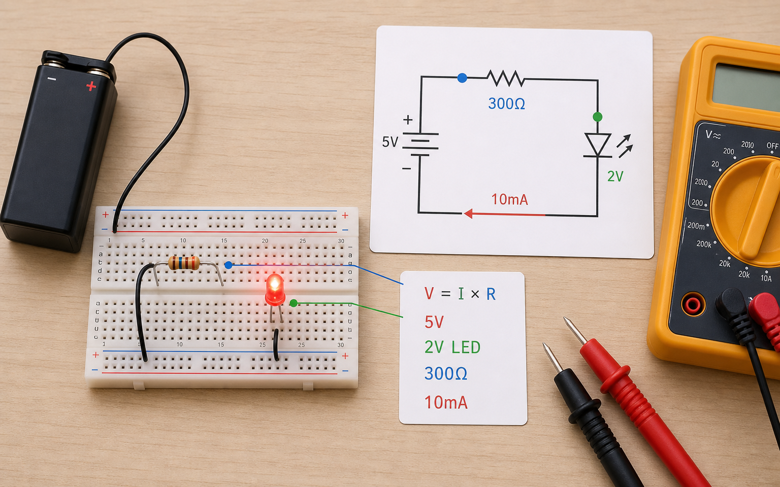
An apprentice who connects an LED directly to a battery is looking, half a second later, at a piece of plastic with a black mark on it. Had he run the numbers, the LED would still be lit. There were three numbers (V, I, R) and the three were tied to a single equation: V = I × R. Until you set this balance in your head, no repair decision turns out right — resistor selection, spare-part calculation, even reading a measurement, all start here.
What kind of balance is there between voltage, current, and resistance?
In a circuit, three numbers always move together: voltage (V), current (I), resistance (R). When you change one, at least one of the others adjusts — this is not a simple arithmetic rule but a physical law of balance. In repair language: if you focus on only one variable on a board, you miss what the other two are quietly doing.
Physically the relationship is this: voltage represents the imbalance between two points, resistance the obstacle this imbalance presents to flow, and current the resulting motion of charge. The formula V = I × R compresses these three into a single line.
The equation opens three interpretations:
- Hold V constant: as R increases, I decreases; as R decreases, I increases. This is the essence of typical LED protection.
- Hold R constant: as V increases, I increases proportionally. The thing to watch when changing an adapter.
- Hold I constant: V and R increase proportionally. Encountered in sensor-supply design.
All three readings are true at the same time — your workshop thinking must carry all three together.
Visual reading: The Ohm's Law triangle — voltage (top, emerald), current (lower left, cyan), resistance (lower right, amber); along the sides, V=I×R, I=V/R, R=V/I; the three tied to one equation.
Why know V = I × R by intuition, not by rote?
Knowing a formula by rote is not enough; in the workshop, a formula is used not just for calculation but for decisions. 'This line is putting out 1.8 V, expected 3.3 V — there is a resistance drop here; what value of resistor produces that difference?' To answer this, you must be able to invert the formula.
Intuitive grasp comes through three moves:
- Single-variable move: Read R = V / I as 'I measured V, I am estimating I, what remains is R that I derive.'
- Sense of direction: As R grows, I shrinks — see this in your mind's eye without looking at the numbers. When the resistance value doubles, halving the current should feel natural.
- Unit cadence: 1 V × 1 A is not 1 Ω; 1 V / 1 A = 1 Ω. That is the definition of the ohm — but in repair, the working units are usually mA and kΩ. You need to know practical ranges like 5 / 470 ≈ 10 mA (that is, 5 V / 470 Ω ≈ 10 mA).
Do not think of the formula only as an equation; place the triangle of three numbers inside your head. V at the top, I and R at the two lower corners — cover one and the math of the other two emerges.
How do we calculate the current-limiting resistor for an LED?
The LED calculation is the most concrete Ohm's-Law application in repair. Because the LED is 'a component with its own voltage drop' (red typically 2 V, blue/white typically 3 V) — if you do not limit the current with a resistor, it does not limit itself, and it can be damaged directly.
The 4 steps of the calculation:
- Write down the source voltage: V_source = 5 V (typical USB)
- Subtract the LED drop: V_LED = 2 V (red LED) → V_resistor = V_source − V_LED (i.e., 5 V − 2 V → 3 V remains)
- Pick a target current: I_target = 10 mA (safe educational range for an LED: 5-20 mA)
- Compute the resistor: R = V_resistor / I_target → R = 3 / 0.010 = 300 Ω → nearest standard value 330 Ω
The output formula: R = (V_source − V_LED) / I.
Practical check — numerical speed:
- 5 V source, 2 V LED, 470 Ω → I = 3 / 470 ≈ 6.4 mA → safe, slightly dim
- 5 V source, 2 V LED, 220 Ω → I = 3 / 220 ≈ 14 mA → safe, bright
- 5 V source, 2 V LED, 100 Ω → I = 3 / 100 ≈ 30 mA → risky; unnecessarily high for most small LEDs
- 5 V source, 2 V LED, 0 Ω (no resistor) → in practice the source and LED limit the current; the LED can be damaged in a short time
Being able to estimate these numbers in your head lets you answer 'how am I going to drive this LED' in 5 seconds at the bench.
Lowering the resistor to make the LED 'a little brighter'
After assembly, an apprentice saw the LED was dim and dropped the resistor from 470 Ω to 100 Ω. The LED really did burn brighter — for a few seconds. Then the light changed, a yellowish glow appeared, and it went out. On the repair board, 3 of the 8 LEDs went the same way. Had the numbers been run, it would have been seen that 100 Ω pushed the current past 30 mA.
The continuous-current rating of many small LEDs is typically around 20 mA; some may be lower or higher, so a datasheet check is required. Lowering the resistor does not change the voltage drop — it raises the current through the remaining voltage. What is assumed to be 'a bit brighter' can turn into a risky current within seconds.
- If the LED is dim, first measure the source voltage and the real current with a multimeter
- Calculate: if I_target is to be increased, invert the formula and let the number come out
- If you are going to change the resistor, verify with the number that I does not exceed 25 mA
How does the current through the same resistor change at different voltages?
The current through a resistor changes directly proportionally to the voltage across it. That is, if you double the voltage, the current doubles too as long as the resistance value stays the same — this is a linear behavior, unlike components with a voltage drop such as LEDs. In repair, resistors are predictable reference points; LEDs or transistors are not as linear.
Quick table (R = 470 Ω constant):
- V = 1 V → I = 1/470 ≈ 2.1 mA
- V = 3 V → I = 3/470 ≈ 6.4 mA
- V = 5 V → I = 5/470 ≈ 10.6 mA
- V = 12 V → I = 12/470 ≈ 25.5 mA
- V = 24 V → I = 24/470 ≈ 51 mA → heat risk becomes pronounced for small resistors
The resistor's power limit (important): A resistor is chosen not only by its resistance value but also by its power rating. The formula P = V × I = V² / R means about 0.3 W of power dissipation for 470 Ω at 12 V; a standard 1/4 W (0.25 W) resistor exceeds this threshold and heats up. At 24 V, the same resistor is about 1.2 W; for a 1/4 W resistor, this is now the damage zone. We will learn the details tomorrow.
Practical workshop reflex: When reading the current on a line, check whether that current is coming through the resistor; if the change is not proportional, the resistor may have opened, its value may have drifted, or it may be approaching a short.
How do we set up the same LED with three different resistors and predict the current first?
Calculation stays abstract; pick up a battery, an LED, and three resistors, and verify the calculation-vs-measurement match yourself. This is preparation for the day you will take real measurements with a multimeter in G5.
Setup:
- 5 V source (USB power bank, or a 9 V battery + 7805 / AMS1117-5V regulator — the source must actually be 5 V; the table below is calculated assuming 5 V)
- Same LED (red, ~2 V drop assumed)
- Three resistors: 220 Ω, 470 Ω, 1 kΩ
Calculation (with paper first, then experiment):
- 220 Ω → I = 3 / 220 ≈ 13.6 mA → bright but safe
- 470 Ω → I = 3 / 470 ≈ 6.4 mA → medium brightness
- 1 kΩ → I = 3 / 1000 ≈ 3.0 mA → visible but faint
Expected observation:
- As the resistor grows, the LED should glow more dimly
- Dimness is not linear — your eye perceives it logarithmically; the difference between 220 Ω and 1 kΩ does not look 'twice as bright', only 'noticeably brighter'
- All 3 LEDs should light; none should burn out
If you get an unexpected result: The LED is installed backwards (won't light), the resistor value is wrong (color-code reading error), or the battery has dropped (source voltage is less than 5 V). Check these three possibilities in order.
Three resistors with the same LED — calculate first, experiment after
On the breadboard, build three separate setups with a 5 V source + LED + 220 Ω / 470 Ω / 1 kΩ resistor. In each one, calculate the current in your head first and note the number. Then compare LED brightness by eye.
Three calculations noted (~13.6 / ~6.4 / ~3.0 mA), and the brightness ordering of the three LEDs is correct: 220 Ω brightest, 1 kΩ faintest.
The 3 calculations written with a pen are correct; in observation, the ordering matches the calculation in direction (brightness ↓ as resistance ↑).
- GUIDESparkFunVoltage, Current, Resistance, and Ohm's Law↗#src_sparkfun_voltage_current_resistance_and_o
- GUIDESparkFunLight-Emitting Diodes (LEDs)↗#src_sparkfun_light_emitting_diodes_leds
- GUIDESparkFunResistors — Power Rating↗#src_sparkfun_resistors_power_rating
- GUIDESparkFunHow to Use a Breadboard↗#src_sparkfun_how_to_use_a_breadboard
What did you gain today?
What you learned today
- V = I × R: three variables tied to one equation; if you change one, at least one of the others adjusts.
- Resistor calculation for an LED: R = (V_source − V_LED) / I_target — the calculation goes wrong if the LED drop is not subtracted.
- For a pure resistor, current changes linearly with voltage; components with a drop, such as LEDs, are not linear.
- Dropping the resistor on intuition to get 'a bit brighter' can quickly push you into a risky current zone; a numerical check is required.
A moment from the field
In a repair workshop, a customer brought in a laptop whose keyboard backlight was burning dimly. The apprentice wanted to drop the current-limiting resistor of the keyboard's LED matrix directly; the master stopped him. When the rail voltage was measured with a multimeter, the line that should have been 3.3 V was reading 2.6 V. The problem was not the resistor but the **regulator on the input side** — the voltage had dropped, so even though the calculation stayed the same, the current had dropped automatically. Had the resistor been swapped, the LEDs would have faced an overcurrent risk; once the voltage was fixed, everything returned to its original state.
What will you learn tomorrow?
Tomorrow we will add the equation of power and energy: P = V × I. The heat across a resistor, the run time of a battery, the capacity of an adapter — all come out of this equation.
Today's Ohm's Law does not stand alone; when power is added tomorrow, it becomes the fourth corner of the same triangle — V, I, R, P. In the repair language, 'current control' now turns into 'power control'.
FREE READING
Keep going — don't lose your place.
You read this lesson without signing up. Checkpoints, progress tracking and the lesson assistant are tied to your account; a free account opens all three and picks up where you left off.
- Checkpoint questions
- Progress tracking
- Lesson assistant
No card required. The free tier stays open with no time limit.
AkademiUsta · CONSOLE.TR · P1_D03