Explain electricity as charge flow and interpret the complete circuit
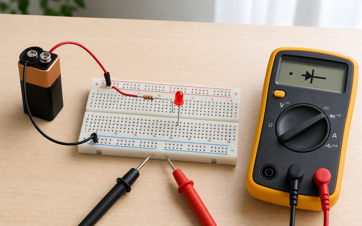
You pick up a board; the LED on it is not lit. You have a battery, you have wires, the LED is intact. But nothing happens. Because something you cannot see is missing: one end of the path is open. For electricity to exist, only one thing is required — a complete return loop. Without understanding this, measurement and diagnosis alike are empty.
Is electricity a thing, or is it a motion?
Speaking of electricity as a 'substance' in the workshop is the first trap everyone falls into. 'Electricity came, went, filled up, drained' — these phrases are easy in language but confuse the mind. Because electricity is not an object, but an event: the motion of charged particles in a particular direction.
Physically, what we call electricity is the flow of electrons along a conductive path. Without that flow, even if the wires are 'full' inside, nothing happens. Note: In schematics and datasheets, the current arrow is generally drawn in the conventional direction (+ → −); inside a metal conductor, electrons drift in the opposite direction. Repair measurements take conventional current direction as the reference — that convention will be used throughout this book. A battery sitting on a wall is unused — its charge is full inside but not flowing. To light a lamp, electrons must pass through the lamp and return.
That is why, in the language of repair, the question 'is there current?' differs from 'is there voltage?'. Voltage may simply be sitting (waiting at the battery terminals), but current happens only on a complete path. As long as your workshop thinking does not make that distinction, every measurement will be misread.
Visual reading: Charge flow concept diagram — in the left panel, electrons move randomly with no voltage applied (net current zero); in the right panel, electrons flow in a definite direction once voltage is applied.
What is charge, and why does it move on its own?
Saying that the electron is the smallest known charge carrier is a starting point in physics class; for workshop intuition, it is not enough. Because the sentence 'the electron has charge' does not explain why it moves. The right question is this: why does charge want to go from one place to another?
The answer is potential difference. The two terminals of a battery are brought to different charge densities by chemical reaction; one end has an excess of electrons, the other has a shortage. This imbalance creates a physical 'pull' — the electrons on the excess side try to move toward the side that is short. But to move, they need a path.
Here is the translation into repair language: when a battery reads 9 V, that is the magnitude of the imbalance between its two terminals. It is not the current — it is the difference that will produce current. The moment you put a conductive path across that difference, the electrons start moving and current begins at that moment. Voltage is the cause, current is the result.
Why is there no current without a complete circuit?
What we call a complete circuit is technically the uninterrupted combination of these four components:
- Source — battery, power supply, USB; produces a potential difference between its two terminals
- Outbound path — the conductor (wire, PCB trace) that goes from the source to the load
- Load — LED, motor, IC; the component that 'uses' the current
- Return path — the conductor that goes from the load back to the other terminal of the source
If any one of the four is broken, the circuit is open and the current is zero. In the workshop, this is the most common reason behind the 'there is voltage but no current' picture: the source is working, the difference is present, but the return path is broken somewhere. In voltage mode, the multimeter reads the voltage (measured statically); in that same mode the current is zero because the circuit is not complete — only when the multimeter is set to current mode and connected in series does it measure the current in a complete circuit.
The complete-circuit rule looks simple on its face, but in workshop practice it produces a critical reflex: if a device will not turn on, first question the path, not the source. The battery may be fine, the IC may be fine; if the ground line is broken in between, nothing works. Half of repair is finding the broken path.
Checking the battery and forgetting the ground line
For a board that would not turn on, an apprentice first measured the battery: 4.0 V. Then he measured the board's power input pin: 4.0 V again. *'The battery is fine, voltage is reaching the board,'* he said, and began swapping the IC. The new IC was installed — same problem. After two hours of removal and rework, the master came over and looked: the wire between the board's GND pad and the battery's negative terminal had broken inside through a micro-crack. It did not show up in the voltage readings because the measurement circuit was closing through another path.
Voltage can be measured even without a complete circuit; the multimeter opens its own high-impedance path and reads the potential difference between the probes. But for current through a load, a fully looped path is needed. The presence of voltage does not imply the presence of current — these two measurements answer different questions.
- First check whether the circuit is complete by using continuity mode
- After the voltage check, confirm that the ground line returns to the source
- Before swapping an IC, look whether the conditions for real current exist at both ends of the path
Where does the conductor / insulator distinction come from in practice?
What determines whether a material is a conductor or an insulator is the density of electrons that can move freely. In the atomic structure of metals, outer-shell electrons are loosely bound — they can shift position even with a small potential difference. In materials such as glass, plastic, or ceramic, the electrons are tightly bound to their atoms, and a very high energy is needed to set them in motion.
For workshop practice, a typical ranking is as follows:
- Excellent conductor: copper, silver, gold (PCB traces, connector pins)
- Moderate conductor: steel, stainless steel, aluminum (housings, screws)
- Weak conductor / semiconductor: silicon, germanium (inside transistors and diodes)
- Insulator: PCB epoxy, cable plastic, air (dry), ceramic
This distinction is not abstract; in repair, it determines decisions in the moment. Where is the measurement probe touching — the copper pad, under the solder mask, or the ceramic body of a capacitor? The answer changes the meaning of the measurement. Placing a probe on the outer body of a capacitor is already placing it at a point outside the circuit; the multimeter showing OL (Over Limit / out of range) does not mean the device is broken.
In addition, humidity weakens an insulator. Dry air is a good insulator, but humid air is a weak conductor; that is why ESD (Phase 1, G1) depends on air humidity, and moisture buildup on a PCB creates hidden leakage currents.
How do we build the simplest circuit with one LED and one battery?
The moment you first see charge flow with your own eyes is the moment you build the simplest complete circuit. Three components are enough: a battery, an LED, and a current-limiting resistor. Without a resistor, connecting an LED directly to a battery — especially a 9 V battery — means instant burnout; that is why the resistor is the first protective reflex learned as inseparable.
Resistor selection range (by source voltage, safe starting zone):
- For a 5 V source: 220 Ω–470 Ω (current ~6–14 mA)
- For a 9 V source: 470 Ω–1 kΩ (current ~7–15 mA)
A lower resistance looks brighter but pushes the LED toward its limit; for beginners, the upper end of the range is preferred.
Step-by-step build (with a 9 V battery):
- Place the battery connection leads onto the breadboard; the red (+) and black (−) should clearly go to separate rails.
- Starting from the (+) rail, place a 470 Ω resistor; the other lead of the resistor should drop into an empty column.
- Connect the LED's long lead (anode, +) to the output of the resistor, and its short lead (cathode, −) to the (−) rail.
- Connect the battery. The LED should light up.
If the LED does not light, there are three possibilities: (a) the LED is installed backwards (orientation matters — a diode passes current only one way), (b) a contact is loose, (c) the resistor is too high.
What does installing the LED backwards teach? It physically shows that a diode is a direction-discriminating component. Current does not flow both ways; it flows only in the anode → cathode direction. This intuition will be deepened in G8, but the first seed is planted here.
Visual reading: Interactive LED current-limiting circuit — current calculation updates live with voltage and resistance sliders; if the resistance is too low, the LED 'burns out' (>30 mA), if too...
Build a complete circuit with a battery + LED + resistor, and run the orientation test
On the breadboard, build a complete circuit with a 9 V battery, a 470 Ω resistor and a standard red LED. First install the LED in the correct orientation, then switch it off and reverse the LED. Observe both states.
The LED lights when in the correct orientation; it does not light when reversed. The circuit structure has not changed — only the LED orientation has.
See the lit LED's light by eye; for the unlit LED, measure the voltage across the resistor with a multimeter — in the correct orientation you should see a drop of V_source − V_LED across the resistor (9 V source + 2 V red LED → ~7 V), and in the reverse direction the LED is an open circuit so the current is zero → the voltage across the resistor is also ~0 V.
- GUIDESparkFunWhat is Electricity?↗#src_sparkfun_what_is_electricity
- GUIDESparkFunVoltage, Current, Resistance, and Ohm's Law↗#src_sparkfun_voltage_current_resistance_and_o
- GUIDESparkFunWhat is a Circuit?↗#src_sparkfun_what_is_a_circuit
- GUIDESparkFunLight-Emitting Diodes (LEDs)↗#src_sparkfun_light_emitting_diodes_leds
What did you gain today?
What you learned today
- Electricity is not a substance — it is the directed motion of charged particles; a complete path is required for current.
- The potential difference at the battery terminals does not *force* the current — it merely *makes it possible*; when a conductive path is provided, electrons flow on their own.
- If any one of the four components of a complete circuit — source, outbound, load, return — is missing, the current is zero; but voltage can still be measured.
- The conductor vs. insulator distinction comes from the density of free electrons; humidity weakens an insulator and creates hidden leakage currents.
A moment from the field
A technician spent four hours on a tablet that would not charge through its USB-C port. With a multimeter she read the correct voltage at every point — USB pin, PMIC input pin, battery connector. Finally, before washing the board and wiping it with clean alcohol, she took an X-ray: the GND pad of the USB-C connector had cracked under the solder joint. Voltage was present everywhere because it was flowing through the signal lines; but the return of the load path was broken. The *'tablet won't turn on'* problem became a *'GND path is broken'* problem.
What will you learn tomorrow?
Tomorrow we will see how voltage, current, and resistance meet in a single equation: Ohm's Law. The idea you sensed today — 'a difference pushes, a path is required' — will turn into a numerical equality tomorrow.
Today's lesson in a single sentence: voltage is the cause, current is the result, and for the result to appear, the path must be complete. Tomorrow, resistance joins this trio.
FREE READING
Keep going — don't lose your place.
You read this lesson without signing up. Checkpoints, progress tracking and the lesson assistant are tied to your account; a free account opens all three and picks up where you left off.
- Checkpoint questions
- Progress tracking
- Lesson assistant
No card required. The free tier stays open with no time limit.
AkademiUsta · CONSOLE.TR · P1_D02